BOSA Oscilloscopes Hardware Description
Tech info | March 25, 2021
BOSA car oscilloscopes are modern measuring instruments designed specifically for service and diagnostics of all types of vehicles, regardless of make or model. They also can be used by all technical specialists in their work on the analysis and problem elimination related to the vehicle's electronic systems.
Basic architecture
BOSA scopes are hardware implemented as an external device communicating with the personal computer via a standard USB interface. This architecture has chosen for several important reasons:
- The functional division of the device into two subsystems - a hardware measuring unit and PC-based computer software. This ensures each of the subsystems to be well-differentiated and facilitates their development for subsequent debugging and improvement.
- The USB interface has become a global standard for the past two decades. It is familiar to anyone who works with a computer. Its use is easy and secure, and there is support in any modern operating system.
- The USB interface provides power to external devices, which is not the case in other standard interfaces, such as LAN, Wi-Fi, Bluetooth, or handheld devices. Learn more about the advantages and disadvantages of the various interfaces used in the modern automotive diagnostic equipment.
- Compared to smartphones, tablets, or handheld devices, the computational power of a modern personal computer (or laptop) is too much more. This fact ensures virtually unlimited opportunities for software development and improvements.
NOTE: BOSA scopes are USB powered devices and do not need aditional power supply.
Sampling resolution
BOSA automotive oscilloscopes are designed to measure high-frequency signals. Depending on the time range and measurement settings, they have two main sampling modes (i.e., converting the analog input signal into a series of numbers):
- Real-Time Sampling. In this mode, the signal is measured only once and is converted into a sequence of numerical points using the maximum operational speed of the analog-to-digital converter (ADC). The sampling rate reaches 2 MS/s per channel. This mode is suitable for measuring both periodic or nonperiodic signals and single impulses.
- Equivalent-Time Sampling. In this method, the analog-to-digital converter operates at maximum frequency, and the signal is measured repeatedly over time. With each new iteration, the digitization starts at a slightly offset moment, and collected points are stored in the memory. After completing the entire cycle of measurements, a general picture is constructed using all samples, arranged accordingly to their time positions. The main advantage of this algorithm is a much higher time resolution (or equivalent sampling rate). In the case of BOSA oscilloscopes, it reaches 70 MS/s on every input channel. Of course, this method is only applicable to strictly periodic signals. It also can be used to observe high-resolution digital signals. One typical example is the shape of the front and back edges in the CAN bus. It can be observed with sufficient details, and the diagnostics of the hardware become easy. However, the decoding of the communication packets themselves will not always be correct.
More about various sampling algorithms and their use in modern car diagnostics.
BOSA scopes have 12-bit voltage resolution on every input channel, in every voltage range, no matter the sampling method been used. The input bandwidth is 1 MHz. Thus, a sufficient time and magnitude resolution of the observed signal also has been ensured.
Ignition test functions
In terms of its basic diagnostic and analysis capabilities, BOSA is an engine tester tool. It has build-in special functions intended to monitor the operation of all electrical components in modern cars. Especially the signals of the sensors and ignition circuits. Along with the observation of standard laboratory signals, the oscilloscope test modes allow:
- Observation and analysis of all types of vehicle sensors.
- Observation and analysis of Primary ignition circuit.
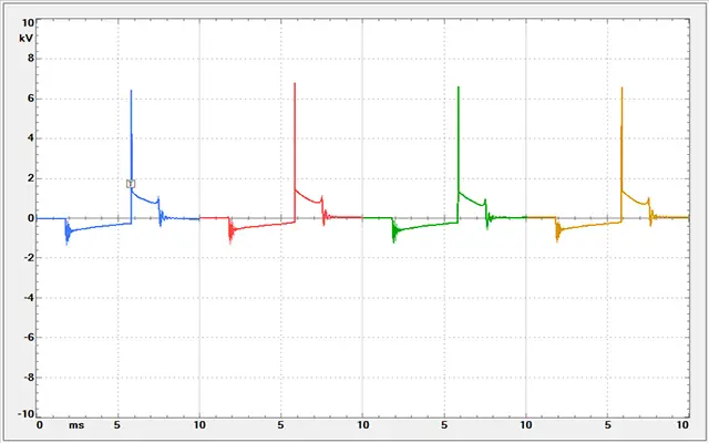
- Ignition pattern visualization for the systems with a mechanical Distributor, Distributorless (DIS) ignition systems with coil on every two spark plugs (Wasted Spark), and Direct Ignition (DI) systems with coil on every spark plug (Coil-On-Plug, COP). The measured signal can be visualized in several different ways: Parade, Raster, Overlay, Single cylinder using additional information of RPMs and the number one cylinder trigger.
- Observation of the fuel injectors operation in gasoline and diesel engines. (Needs additional attenuators to be plugged into the oscilloscope's inputs).
- Ignition current measurement. (Needs a current clamp to be used).
- In-cylinder Pressure ratio measurement (using Pressure Transducer).
- Pressure pulse variations of the exhausted gasses measurement (using Pressure Pulse Sensor).
- Complete analysis of the vibrations and overall mechanical condition of the engine to be done (using an additional Vibration Transducer).
- Slow variable signals observation. Examples are Oxygen Sensor (Lambda Probe) and Coolant Temperature Sensor (ECT) signals.
- CAN bus diagnostics.
- Car battery check.
- General measurements of periodic and impulse electric signals.
More info about different measuring modes and their settings you can find on our automotive diagnostic software page.
The BOSA automotive oscilloscope uses a USB interface to connect to a personal computer. Although providing data transfer at a high enough rate, USB communication, by its nature, is accomplished using discrete data packets over time. When the hardware receives a measurement request, it starts it and waits for its completion. Then, it sends the collected data to the computer via USB. The graphics software processes the received package, prepares the result and displays it on the screen. Of course, all this takes some time, typically about 20 ms. The software must process data, and the operating system is responsible for refreshing the picture on the computer screen. Only then, another measurement request is sent again to the hardware. The whole cycle repeats. The process described so far is synchronous, ensuring stability and predictability.
So far, so good. The described sequence works, and it is typical for all modern digital oscilloscopes. A closer look at this process, however, shows that there is one peculiarity. The problem is such that in the intervals between two consecutive cycles, what happens to the signal remains invisible. Even more, the measured signal may contain some sporadic components. It is not unusual if they are falling into the intervals between successive measurements. In this situation, we have no way to know about them. And in such an interval can be placed many periods of the observed signal. Thus, we will lose too much important information.
To solve such kinds of problems, BOSA includes a special sampling mode called Stream. In this mode, data transfer to the PC is in real-time and without interruption. The memory of the hardware unit is divided into several blocks, filled sequentially with new data. When the current block finishes, it is submitted to the memory controller for automatic transfer to the computer via the USB interface. Meanwhile, data acquisition continues in the next block, without interruption, etc. The process described here is asynchronous. Thus, while the computer processes and displays the next portion of data, the hardware unit continues in real-time with data acquisition. The maximum speed in this mode is 100 kS/s for one channel. The amount of data collected depends on the overall buffer size set in the computer's memory. For example, let the maximum sampling rate is 100 kS/s, and we are using the 8-bit acquisition mode. Let the allocated buffer is 1 GB (this is not a problem for modern personal computers). Then, the measurement will take almost three hours. That is pretty enough for many of the diagnostic tasks. This mode is suitable for monitoring fast random processes by looking for problems that are not always clear and predictable. A typical example is monitoring the operation of the Crankshaft Position Sensor or the Camshaft Position Sensor.
Read more about sampling algorithms, implemeted in BOSA oscilloscopes and their use in modern vehicle diagnostics.
Full galvanic isolation
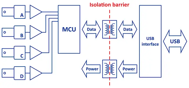
BOSA scopes have full galvanic isolation between measuring input circuits on one side and the USB interface with the PC on the other. The isolation is on the data lines and the power lines. The entire measuring unit of the oscilloscope has a floating ground. It is completely isolated from the interface block, the last one being responsible exceptionally for the data transfer to and from the computer. What are the advantages of this architecture? Above all, the safety of the equipment and the technician using the oscilloscope. In the process of work, some situations can arise that are potentially dangerous. For example, when measuring the secondary ignition circuit, we may have a compromised insulation spark plug cable. That can lead to an electric shock through the inputs of the oscilloscope. Both the equipment itself and the person working with it may be affected. And although the current in the secondary circuit is too small, and hence the pulse energy is generally negligible, it is still a voltage of tens of kilovolts. In this situation, protective measures, such as galvanic isolation, must be considered. And something more. By separating the hardware unit from the personal computer, it is possible to eliminate the high-frequency interference and noise passing through the USB interface. Sometimes they cause some very unpleasant hangs
during the oscilloscope's operation, with the need for a subsequent restart of the system.
Additional information about isolation standards used in BOSA oscilloscopes, you can find in the User Manual.
Input protection
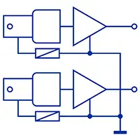
Sometimes, while working with the oscilloscope, the technician can accidentally connect two voltage sources with reversed polarity. That may happen just because of some momentary lapse of attention, for example. That situation most often occurs if we use two probes simultaneously connected to the oscilloscope's inputs. The other side of the first probe is connected correctly to the measured source, with its ground terminal connected to the car's chassis ground. At the same time, the ground terminal of the second probe connects (or just touches) the positive pole of the car's battery. Thus, a short circuit occurs through the oscilloscope's inputs. That will damage the device and certainly is not so good for the battery itself. BOSA oscilloscopes have a short-circuit protection between individual inputs to prevent extreme situations similar to those described above. Each of the oscilloscope's inputs also has overvoltage protection in the range ±350 V AC/DC.
WARNING: Never leave the oscilloscope for a long time (more than a minute) with the reverse polarity voltage sources connected to its inputs! Even if the instrument is disconnected from the power supply, this will cause input protection to overheat with possible device damage.
Trigger system
The trigger system in BOSA automotive oscilloscopes is fully hardware implemented. That ensures a much more accurate determination of significant events in the measured signal. Hence, the picture on the screen is much more stable and easy to use. In many modern car scopes, the trigger system is only in software or completely missing. In this case, on every measurement, a huge amount of data points (of the order of millions and tens of millions) are collected at the maximum sampling rate and then transmitted to the processor for further analysis. From here, there are two main approaches. In the first one, complicated software algorithms pass through all data points and determine the exact moments in the measured signal. Then, depending on the settings, a static picture is constructed
with a small part of the array and displayed on the oscilloscope screen. In the second approach, the entire data array is divided into smaller successive portions (screens) and displayed sequentially for viewing with the possibility of additional magnification (zoom).
Okay, but what's wrong with the software trigger? Well, the thing is that the time resolution, in this case, is limited to the sampling period (i.e., the time during which the successive measurement points are taken). The significant events in the observed signal can fall between data points and thus, be missed. On the other hand, viewing the huge amount of information accumulated in the device memory is a time-consuming operation and takes significant system resources.
The most important advantage of the hardware trigger is the response time of the whole system, which is tens (even more!) times less than the sampling period. The significant moments in the observed signal are determined with a much higher time resolution. In general, the operation of the system is more secure and predictable. Therefore, the displayed picture is much more stable and reliable.
More about settings and trigger modes you can find on our StudioBOSA automotive software description page.
Read more about sampling algorithms in BOSA diagnostic oscilloscopes. On the library page you can find additional information about some of our interesting scientific works. If you have more questions about BOSA scopes, please visit our contact page and call us.