StudioBOSA Diagnostic Software
Tech info | April 18, 2021
StudioBOSA™ is an automotive diagnostic software application with a modern graphical user interface. The program is based on the Microsoft Windows Framework .NET and is designed to work with BOSA oscilloscopes. The software is easy to use, with a simple and intuitive interface, while giving all the necessary instruments for use and operation. Modern automotive diagnostics requires for cleanliness and versatility of such applications. The everyday activity of service specialists needs an affordable and reliable tool, which can help them to find the exact solution for many of the problems related to vehicle maintenance. BOSA diagnostic oscilloscopes, along with the StudioBOSA application, are created to meet all these requirements. They are an excellent choice in supporting the work of service professionals.
Operating modes
StudioBOSA graphical interface changes according to the measurement mode been set. Each component of the work screen can reshape its appearance and content as a function of the current settings. This flexibility makes using the program easy and intuitive.
StudioBOSA has two main groups of operating modes, based on their purpose:
-
Universal modes. They are suitable to measure periodic or nonperiodic signals in a wide range as well as single impulses. Periods can be from microseconds to tens and hundreds of minutes. These modes are available under Modes menu.
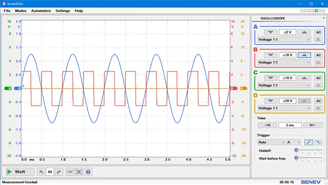
- Oscilloscope. Universal digital storage lab scope.
- Stream. Intended to observe signals with periods ranging from one second to minute. A typical example is the Oxigen Sensor signal (Lambda Probe).
- Slow Variable. Intended to observe signals with periods ranging from one minute to one hour and more. For example, the Coolant Temperature Sensor (ECT) signal.
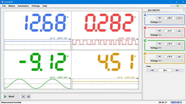
- Multimeter. Shows the measurement result in digits.
-
Ignition test modes. Specially designed and intended to observe the signals in Primary and Secondary Ignition Systems. These modes are available under Automotive menu.
- Sparkscope. The mode is similar to the Oscilloscope mode but is designed to measure signals in the ignition circuits. It can display the high-frequency breakdown voltage events with enhanced accuracy. More about Sparkscope mode.
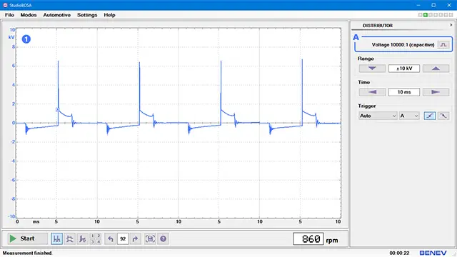
- Distributor. Shows ignition patterns in the systems with mechanical Distributor.
- DIS – Wasted Spark. Shows ignition patterns in the Distributorless (DIS) systems with single coil on two spark plugs.
- DI – Coil-On-Plug. Shows ignition patterns in the Direct Ignition (DI) systems with single coil on every spark plug.
NOTE: StudioBOSA has a built-in Demo mode, which allows you to see the operation of the oscilloscope and software in the maximum degree of accuracy. This mode can be used regardless of the presence of a hardware unit. Demo mode is under the Settings → Demo mode.
NOTE: StudioBOSA has a mode-sensitive build-in Help system that allows a quick and easy way to get the specific information of current working mode and operational procedures.
Detailed information about each operational mode, its use and specific settings can be found in the oscilloscope's User Manual.
Input ranges
For each of the oscilloscope channels, the technician can select the following input ranges:
- Voltage 1:1.
- Voltage 10:1. A 10:1 attenuator is needed.
- Voltage 20:1. A 20:1 attenuator is needed
- Current ±20 A (1 mV / 10 mA). Used with current clamps.
- Current ±60 A (1 mV / 100 mA). Used with current clamps.
- Current ±600 A (1 mV / 1 A). Used with current clamps.
- Voltage 10000:1. This range is available only in the automotive modes. A 10000:1 capacitive pick-up clamps should be used!
In each of the listed ranges, the application allows additional settings of the input coupling (AC / DC) and signal inversion for each channel to be selected.
The application provides an option for the channel's graphics to be offset along the vertical axis. That ensures a better visualization of the observed signal. It is done by clicking and dragging the numerical bar of the selected channel in the vertical direction. You can learn more in the oscilloscope's User Manual.
Trigger settings
BOSA diagnostic oscilloscopes have a hardware trigger system, and the application allows you to set the following trigger settings:
- Trigger level. Set by moving the trigger marker vertically in the graphics panel. The level is full range. In Sparkscope mode, the trigger level is set independently for each input channel using additional trigger markers.
- Pretrigger. Set by moving the trigger marker horizontally in the graphics panel or by clicking and dragging the time bar. It can be adjusted from 0 to 95%.
- Trigger mode: Auto, Free, Single (Waiting).
- Trigger channel.
- Trigger edge: Rising, Falling. In Sparkscope mode, the trigger edge can be set independently for every input channel.
- Time-to-wait. Set the time interval before Auto trigger mode to switch in Free mode in the case the trigger event is not present.
- Holdoff. It stabilizes the picture of the complex digital signals.
More information about oscilloscope's trigger system you can find on the BOSA technical specification page.
Ignition test modes
StudioBOSA includes a set of special test functions designed to visualize the signals in the primary and secondary ignition circuits of the vehicle.
Because of the specifics in the ignition signals and to facilitate the service technicians in their work, these modes have preset measurement settings. The trigger activates for each cylinder at the moment around the fuel mixture ignition. For a four-cylinder engine, a firing sequence 1-3-4-2 is assumed. In the intervals between the individual acts of combustion, the oscilloscope is in standby mode and does not collect any data. That makes it possible to record a detailed picture with a high enough time resolution. Collected data are shown in several view modes on the oscilloscope's screen:
- Parade (parade of cylinders). The ignition patterns are side-by-side.
- Raster. The ignition patterns are one under another.
- Overlay. The ignition patterns are one over another in the same place.
- Single. Shows the ignition pattern for a single cylinder only.
In each of the ignition modes, the value of the RPM is shown. It is also possible to invert the signal of each cylinder, regardless of the display mode. When performing a measurement on a distributor system, there is an option to synchronize on the first cylinder using an inductive pick-up. That ensures a correct cylinder order on the screen. In Oscilloscope mode and Sparkscope mode, there is the ability to measure time intervals in degrees from 0° to 720°.
WARNING: The special ignition modes should be used only with the high-voltage 10000:1 capacitive pick-up clamps! Using standard oscilloscope leads and probes will cause serious damage to the instrument!
More about special ignition test modes you can read on the hardware description page and in the oscilloscope's User Manual.
Installation
You can download StudioBOSA from the BOSA oscilloscope page download section. The application does not need any installation at all. Just unpack the zip archive somewhere on your system, for example, in C:\Program Files\StudioBOSA and run the .exe file. Additionally, you can create a shortcut on your Desktop or Start menu.
NOTE: The archive contains an executable file. Some antivirus software may restrict it from the download. Please, check the settings of your antivirus program.
NOTE: Do not change the structure and content of the unpacked zip archive.
NOTE: For driver installation, please refer to the automotive oscilloscope's User Manual.
On the library page you can read more about some of our interesting scientific works. If you have more questions about our products, visit contact page and call us.